Práctica 2 con GNS3
Video
Video para instalar un switch capa 3 en gns3
Montaje
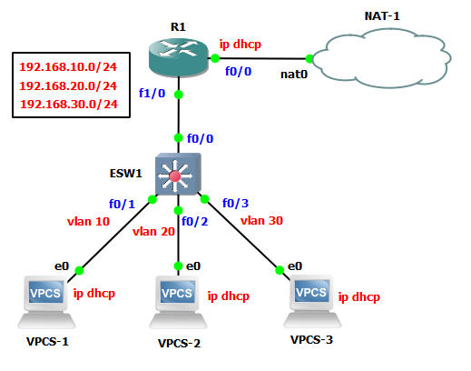
Realizamos el siguiente montaje:

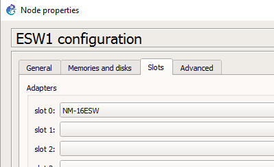
En el switch cambiamos la configuración del slot.

Configuración del Router
Configuramos la interfaz f0/0 en el router
  R1#configure terminal
  Enter configuration commands, one per line.  End with CNTL/Z.
  R1(config)#interface fastEthernet 0/0
  R1(config-if)#ip address dhcp
  R1(config-if)#no shutdown
  R1(config-if)#e
  *Jan 18 13:17:47.199: %LINK-3-UPDOWN: Interface FastEthernet0/0, changed state to up
  *Jan 18 13:17:48.199: %LINEPROTO-5-UPDOWN: Line protocol on Interface FastEthernet0/0, changed state to up
  R1(config-if)#exit
  R1(config)#exit
  R1#
  *Jan 18 13:17:55.183: %SYS-5-CONFIG_I: Configured from console by console
  R1#ping 8.8.8.8
  *Jan 18 13:18:02.059: %DHCP-6-ADDRESS_ASSIGN: Interface FastEthernet0/0 assigned DHCP address 192.168.122.164,
  mask 255.255.255.0, hostname R1
Esperamos un poco a que el router coja una ip (en mi caso, 192.168.122.164)
  R1#ping 8.8.8.8
  Type escape sequence to abort.
  Sending 5, 100-byte ICMP Echos to 8.8.8.8, timeout is 2 seconds:
  !!!!!
  Success rate is 100 percent (5/5), round-trip min/avg/max = 16/20/36 ms
  R1#
Succes rate => Conexión a internet correcta.
Vemos la configuración de ips en el router.
  R1#sh ip int br

  Interface              IP-Address      OK? Method Status                Protocol
  FastEthernet0/0        192.168.122.164 YES DHCP   up                    up
  FastEthernet1/0        unassigned      YES unset  administratively down down
  FastEthernet1/1        unassigned      YES unset  administratively down down
  R1#
Configuramos la interfaz f1/0 en el router
Activamos el puerto f1/0 y creamos las 3 subinterfaces para las vlans.
R1#configure terminal
Enter configuration commands, one per line.  End with CNTL/Z.
R1(config)#interface f1/0
R1(config-if)#no shutdown
R1(config-if)#exit
R1(config)#
*Jan 18 13:22:41.867: %LINK-3-UPDOWN: Interface FastEthernet1/0, changed state to up
*Jan 18 13:22:42.867: %LINEPROTO-5-UPDOWN: Line protocol on Interface FastEthernet1/0, changed state to up
R1(config)#interface f1/0.10
R1(config-subif)#encapsulation dot1Q 10
R1(config-subif)#ip address 192.168.10.1 255.255.255.0
R1(config-subif)#exit
R1(config)#interface f1/0.20
R1(config-subif)#encapsulation dot1Q 20
R1(config-subif)#ip address 192.168.20.1 255.255.255.0
R1(config-subif)#exit
R1(config)#interface f1/0.30
R1(config-subif)#encapsulation dot1Q 30
R1(config-subif)#ip address 192.168.30.1 255.255.255.0
R1(config-subif)#exit
R1(config)#
Vemos la configuración:
R1#show ip interface brief
Interface              IP-Address      OK? Method Status                Protocol
FastEthernet0/0        192.168.122.164 YES DHCP   up                    up
FastEthernet1/0        unassigned      YES unset  up                    up
FastEthernet1/0.10     192.168.10.1    YES manual up                    up
FastEthernet1/0.20     192.168.20.1    YES manual up                    up
FastEthernet1/0.30     192.168.30.1    YES manual up                    up
FastEthernet1/1        unassigned      YES unset  administratively down down
R1#
Configuramos las VLAN en el router
R1#configure terminal
Enter configuration commands, one per line.  End with CNTL/Z.
R1(config)#ip dhcp pool VLAN10
R1(dhcp-config)#network 192.168.10.0 255.255.255.0
R1(dhcp-config)#default-router 192.168.10.1
R1(dhcp-config)#dns-server 8.8.8.8
R1(dhcp-config)#exit
R1(config)#ip dhcp pool VLAN20
R1(dhcp-config)#network 192.168.20.0 255.255.255.0
R1(dhcp-config)#default-router 192.168.20.1
R1(dhcp-config)#dns-server 8.8.8.8
R1(dhcp-config)#exit
R1(config)#ip dhcp pool VLAN30
R1(dhcp-config)#network 192.168.30.0 255.255.255.0
R1(dhcp-config)#default-router 192.168.30.1
R1(dhcp-config)#dns-server 8.8.8.8
R1(dhcp-config)#exit
R1(config)#ip dhcp excluded-address 192.168.10.1 192.168.10.99
R1(config)#ip dhcp excluded-address 192.168.10.150 192.168.10.255
R1(config)#ip dhcp excluded-address 192.168.20.1 192.168.20.49
R1(config)#ip dhcp excluded-address 192.168.20.100 192.168.20.255
R1(config)#exit
R1#
*Jan 18 13:34:54.303: %SYS-5-CONFIG_I: Configured from console by console
R1#
Configuración del Switch
Creamos las VLAN en el Switch
ESW1#vlan database
ESW1(vlan)#vlan 10 name VLAN10
VLAN 10 modified:
    Name: VLAN10
ESW1(vlan)#vlan 20 name VLAN20
VLAN 20 modified:
    Name: VLAN20
ESW1(vlan)#vlan 30 name VLAN30
VLAN 30 modified:
    Name: VLAN30
ESW1(vlan)#exit
APPLY completed.
Exiting....
ESW1#
Vemos como nos queda:
ESW1#show vlan-switch
VLAN Name                             Status    Ports
---- -------------------------------- --------- -------------------------------
1    default                          active    Fa0/0, Fa0/1, Fa0/2, Fa0/3
                                                Fa0/4, Fa0/5, Fa0/6, Fa0/7
                                                Fa0/8, Fa0/9, Fa0/10, Fa0/11
                                                Fa0/12, Fa0/13, Fa0/14, Fa0/15
10   VLAN10                           active
20   VLAN20                           active
30   VLAN30                           active
1002 fddi-default                     active
1003 token-ring-default               active
1004 fddinet-default                  active
1005 trnet-default                    active
VLAN Type  SAID       MTU   Parent RingNo BridgeNo Stp  BrdgMode Trans1 Trans2
---- ----- ---------- ----- ------ ------ -------- ---- -------- ------ ------
1    enet  100001     1500  -      -      -        -    -        1002   1003
10   enet  100010     1500  -      -      -        -    -        0      0
20   enet  100020     1500  -      -      -        -    -        0      0
30   enet  100030     1500  -      -      -        -    -        0      0
1002 fddi  101002     1500  -      -      -        -    -        1      1003
1003 tr    101003     1500  1005   0      -        -    srb      1      1002
1004 fdnet 101004     1500  -      -      1        ibm  -        0      0
1005 trnet 101005     1500  -      -      1        ibm  -        0      0
ESW1#
Asignamos a cada interfaz su vlan
La f0/0 la configuramos como troncal (trunk)
ESW1#configure terminal
Enter configuration commands, one per line.  End with CNTL/Z.
ESW1(config)#int f0/0
ESW1(config-if)#switchport trunk encapsulation dot1q
ESW1(config-if)#switchport trunk all vlan all
ESW1(config-if)#switchport mode trunk
ESW1(config-if)#no sh
ESW1(config-if)#
*Mar  1 00:20:36.779: %DTP-5-TRUNKPORTON: Port Fa0/0 has become dot1q trunk
ESW1(config-if)#
*Mar  1 00:20:38.139: %LINEPROTO-5-UPDOWN: Line protocol on Interface FastEthernet0/0, changed state to up
ESW1(config-if)#exit
ESW1(config)#int f0/1
ESW1(config-if)#switchport access vlan 10
ESW1(config-if)#no sh
ESW1(config-if)#exit
ESW1(config)#
*Mar  1 00:21:45.343: %LINEPROTO-5-UPDOWN: Line protocol on Interface FastEthernet0/1, changed state to up
ESW1(config)#int f0/2
ESW1(config-if)#switchport access vlan 20
ESW1(config-if)#no sh
ESW1(config-if)#exit
ESW1(config)#int f0/3
ESW1(config-if)#switchport access vlan 30
ESW1(config-if)#no sh
ESW1(config-if)#exit
ESW1(config)#exit
ESW1#
*Mar  1 00:22:41.035: %SYS-5-CONFIG_I: Configured from console by console
ESW1#
Vemos la configuración:
ESW1#show ip interface brief
Interface                  IP-Address      OK? Method Status                Protocol
FastEthernet0/0            unassigned      YES unset  up                    up
FastEthernet0/1            unassigned      YES unset  up                    up
FastEthernet0/2            unassigned      YES unset  up                    up
FastEthernet0/3            unassigned      YES unset  up                    up
FastEthernet0/4            unassigned      YES unset  up                    down
FastEthernet0/5            unassigned      YES unset  up                    down
FastEthernet0/6            unassigned      YES unset  up                    down
FastEthernet0/7            unassigned      YES unset  up                    down
FastEthernet0/8            unassigned      YES unset  up                    down
FastEthernet0/9            unassigned      YES unset  up                    down
FastEthernet0/10           unassigned      YES unset  up                    down
FastEthernet0/11           unassigned      YES unset  up                    down
FastEthernet0/12           unassigned      YES unset  up                    down
FastEthernet0/13           unassigned      YES unset  up                    down
FastEthernet0/14           unassigned      YES unset  up                    down
FastEthernet0/15           unassigned      YES unset  up                    down
Vlan1                      unassigned      YES NVRAM  administratively down down
ESW1#
Vemos la tabla con las vlan y vemos que la interfaz Fa0/1 está la vlan 10, la Fa0/2 está en la vlan 20 y la Fa0/3 está en la vlan 30.
ESW1#show vlan-switch
VLAN Name                             Status    Ports
---- -------------------------------- --------- -------------------------------
1    default                          active    Fa0/4, Fa0/5, Fa0/6, Fa0/7
                                                Fa0/8, Fa0/9, Fa0/10, Fa0/11
                                                Fa0/12, Fa0/13, Fa0/14, Fa0/15
10   VLAN10                           active    Fa0/1
20   VLAN20                           active    Fa0/2
30   VLAN30                           active    Fa0/3
1002 fddi-default                     active
1003 token-ring-default               active
1004 fddinet-default                  active
1005 trnet-default                    active
VLAN Type  SAID       MTU   Parent RingNo BridgeNo Stp  BrdgMode Trans1 Trans2
---- ----- ---------- ----- ------ ------ -------- ---- -------- ------ ------
1    enet  100001     1500  -      -      -        -    -        1002   1003
10   enet  100010     1500  -      -      -        -    -        0      0
20   enet  100020     1500  -      -      -        -    -        0      0
30   enet  100030     1500  -      -      -        -    -        0      0
1002 fddi  101002     1500  -      -      -        -    -        1      1003
1003 tr    101003     1500  1005   0      -        -    srb      1      1002
1004 fdnet 101004     1500  -      -      1        ibm  -        0      0
1005 trnet 101005     1500  -      -      1        ibm  -        0      0
ESW1#
PC1. Configura y comprobamos que no va internet
Coge una ip de la vlan 10: 192.168.10.100, pero no conecta a internet.
  VPCS-1> ip dhcp
  DDORA IP 192.168.10.100/24 GW 192.168.10.1
  VPCS-1> ping 8.8.8.8
  8.8.8.8 icmp_seq=1 timeout
  8.8.8.8 icmp_seq=2 timeout
  8.8.8.8 icmp_seq=3 timeout
8.8.8.8 icmp_seq=4 timeout8.8.8.8 icmp_seq=5 timeout
VPCS-1>
PC2. Configura y comprobamos que no va internet
Coge una ip de la vlan 10: 192.168.20.50, pero no conecta a internet.
  VPCS-2> ip dhcp
  DDORA IP 192.168.20.50/24 GW 192.168.20.1
  VPCS-2> ping 8.8.8.8
  8.8.8.8 icmp_seq=1 timeout
  8.8.8.8 icmp_seq=2 timeout
  8.8.8.8 icmp_seq=3 timeout
  8.8.8.8 icmp_seq=4 timeout
  8.8.8.8 icmp_seq=5 timeout
VPCS-2>
PC3. Configura y comprobamos que no va internet
Coge una ip de la vlan 10: 192.168.30.2, pero no conecta a internet.
  VPCS-3> ip dhcp
  DDORA IP 192.168.30.2/24 GW 192.168.30.1
  VPCS-3> ping 8.8.8.8
  8.8.8.8 icmp_seq=1 timeout
  8.8.8.8 icmp_seq=2 timeout
  8.8.8.8 icmp_seq=3 timeout
  8.8.8.8 icmp_seq=4 timeout
  8.8.8.8 icmp_seq=5 timeout
VPCS-3>